
Overload and Step-Load Tests for Shore Power Systems
A shore power load test is only meaningful when it reproduces a defined operating condition, measures the response at the correct electrical boundary and uses acceptance criteria agreed before the test starts.
A rated-load test, overload test, step-load test and load-rejection test prove different things. Rated load verifies continuous operation. Overload verifies temporary duty above continuous rating. Step-load testing measures dynamic voltage, frequency and current response, while load rejection evaluates what happens when a significant load disappears rapidly.
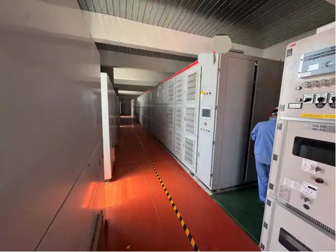
Start with the Vessel Operating Event
The correct shore power test case begins with an operating event, not with a percentage.
A vessel can create several types of demand changes: a large motor starting, several auxiliary loads starting within a short period, a large pump stopping, a group of loads disconnecting, a temporary peak above normal demand, an unbalanced phase condition or a transfer between ship generation and shore supply.
These events do not stress the system in the same way.
A motor start can create a rapid increase in current and a temporary voltage depression. Load rejection can produce voltage or frequency overshoot. A temporary peak above continuous rating creates thermal and current-limit questions. Unequal phase loading tests phase regulation rather than only total kVA capacity.
First identify the vessel event that the test is intended to reproduce. A change from 0% to 30% rated load is not the same event as a change from 70% to 100%, even though the percentage increase is the same.
The vessel load list, largest motors, motor-starting method, simultaneous loads and expected operating sequence should therefore be reviewed before the test method is frozen.
Our shore power selection and compatibility guide explains the vessel and shore-side information needed before configuration and testing are finalized.
Four Load Tests, Four Different Questions
| Test | Main engineering question | Typical evidence |
|---|---|---|
| Rated-load test | Can the system operate continuously at specified output? | Voltage, current, power, temperature, cooling and stability |
| Overload test | Can the system carry more than continuous rating for an agreed time? | Current, duration, temperature and protection behaviour |
| Step-load application | What happens when load increases quickly? | Voltage/frequency deviation, current response and recovery |
| Load rejection | What happens when a significant load is removed rapidly? | Overshoot, controller response and protection behaviour |
Passing one of these tests does not automatically prove the others.
A converter can operate correctly at full rated load for an extended period and still respond poorly to a sudden motor start. It can also show excellent step-load recovery for a few seconds while exceeding thermal limits during a sustained overload.
From Vessel Event to Test Case
Dynamic testing becomes easier to define when the operating concern is translated into a test case.
| Operating concern | Test condition | Main measurement | What the result tells us |
|---|---|---|---|
| Large auxiliary load starts | Defined load application | Voltage, frequency, current | Dip, current response and recovery |
| Large load disconnects | Defined load rejection | Voltage and frequency | Overshoot and control stability |
| Temporary peak above rating | Timed overload | Current and temperature | Thermal and current-carrying capability |
| Long continuous demand | Rated-load run | Electrical values and temperature | Continuous-duty capability |
| Unequal phase loading | Controlled phase imbalance | Phase voltage and current | Phase regulation and loading |
| Repeated operating events | Repeated transitions | Response and temperature trend | Repeatability and thermal accumulation |
The percentages and acceptance limits in this matrix must come from the actual vessel and project requirements. The matrix is a way to make each test traceable to a real operating concern.
What a Real Shore Power Load-Test Setup Includes
A meaningful shore power load test requires more than connecting a fixed resistor to the converter output.
One project load-test arrangement for low-voltage ship supply used 500/630 kVA-class test equipment together with AC load banks, step-down transformers and the required interconnection cables.
The load equipment included resistive and inductive loading, data acquisition, controlled load addition and removal, protection, cooling and electrical control.
- Resistive load provides controlled active-power demand.
- Inductive load helps reproduce reactive-power conditions.
- Controlled switching creates repeatable load application and rejection.
- Data acquisition records the electrical state before, during and after the event.
- Cooling and protection keep the load equipment within its own safe operating envelope.
This matters because the test setup determines what the result actually proves.
A purely resistive load bank may verify kW loading, but it does not reproduce the same reactive-power behaviour as a vessel with large motors and inductive auxiliary loads.

For a dynamic test, the measuring equipment must also capture the event fast enough to show the pre-event state, load transition, maximum deviation, recovery behaviour and relevant protection actions.
Overload Magnitude and Duration Must Be Paired
“110% overload” is not a complete engineering requirement.
If a converter must support more than its continuous rating, the complete current path must also support that duty.
The converter, transformer, busbars, switchgear and cables may not all have the same temporary current capability.
One project test procedure used a 110% rated-current condition for a 60-minute overload verification. That is useful project evidence, but it is not a universal requirement for every shore power system.
Cold, Hot and Repeated Tests Are Not Equivalent
The same electrical load event can produce a different result when the thermal starting condition changes.
Cold equipment
Semiconductor junctions, transformer windings, cables and enclosure air start with greater thermal margin.
After continuous full-load operation
The system begins the next event with higher component and cooling-system temperatures.
Repeated events
Several load steps or overload events within a short period can accumulate heat even when each individual event is within its allowed duration.
The recovery interval between repeated tests should therefore be part of the procedure when repeated vessel events are credible.
A dynamic test performed before full-load thermal stabilization is not the same starting condition as the same test performed after sustained operation.
Step-Load Testing Measures Dynamic Response
In a shore power step-load test, a defined block of load is added quickly and the electrical response is recorded before, during and after the transition.
The load step should be stated both as actual kW or kVA and as a percentage of system rating.
“25% load step” gives much less information than “150 kW added from a 600 kW initial operating condition on a 1,000 kW system.”
Power factor also matters. A resistive step and an inductive step do not impose the same active and reactive demand on the converter and transformer.
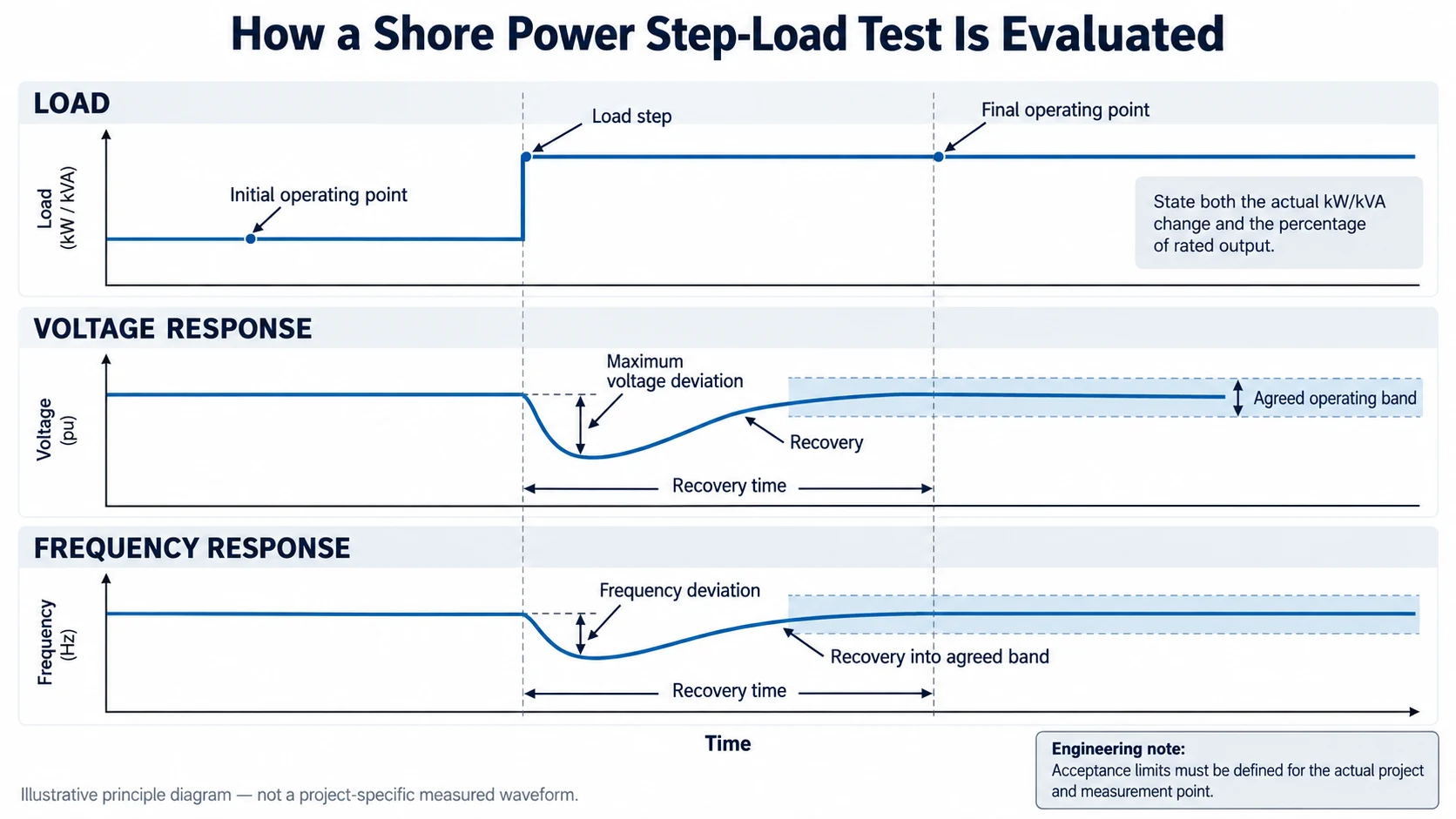
The main measurements normally include output voltage, phase current, frequency, active power, reactive power, power factor, alarms and protection status.
One engineering procedure used a 20–30% load adjustment for waveform and transient-response checks. That range belonged to that project and should not be reused as a universal acceptance requirement.
Load Rejection Deserves Its Own Test
Dynamic testing should not examine only increasing load.
When a large block of vessel load disconnects, converter demand falls rapidly. The control system then has to move from the previous operating point to a much lower one.
This transition can reveal temporary voltage rise, frequency deviation, controller overshoot, oscillatory recovery or nuisance protection behaviour.
The initial load is important. Rejecting a given load block from a low operating point is not the same as removing it from full load.
The test should identify both the load removed and the operating point before rejection.
Unbalanced Load Testing Checks a Different System Limit
A balanced three-phase load bank does not reproduce every vessel operating condition.
If substantial phase imbalance is expected, the test procedure may need controlled unequal phase loading.
Useful measurements include:
- individual phase voltage;
- individual phase current;
- voltage unbalance;
- current unbalance;
- converter phase loading;
- transformer winding loading.
Voltage unbalance and current unbalance should be treated as separate measurements. A load bank that cannot independently control phase loading cannot fully reproduce an intentional unbalanced-load condition.
Factory FAT and Site Load Testing Prove Different Boundaries
Factory testing and site testing can use similar load events, but they do not necessarily prove the same system.
At the factory, the test boundary may end at the converter or packaged shore power equipment. This controlled environment is useful for verifying converter operation, protection, regulation, cooling, overload capability and dynamic response.
After installation, the power path can include additional transformer impedance, output switchgear, long cable runs, connection equipment and the vessel interface.
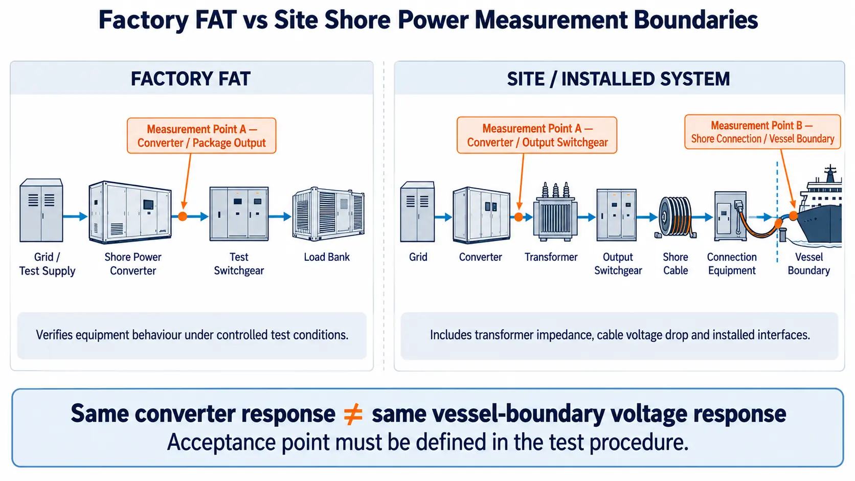
A converter-terminal voltage that recovers correctly does not automatically prove that the vessel connection experiences the same voltage response.
Measure at the Converter and at the Delivery Boundary
Measurement location is one of the most important parts of a dynamic test specification.
A useful project may define one measurement point at the converter or output switchgear and another at the final shore connection or vessel-delivery boundary.
Cable length, conductor size and operating current should also be recorded where downstream voltage drop is relevant.
The same principle applies to harmonics and other power-quality quantities. A value without a defined measurement point and load condition is difficult to compare with another test result.
Our article on shore power harmonics and power quality explains this measurement-location issue in more detail.
Dynamic Response Does Not Replace Full-Load Thermal Testing
A step-load event may be completed within seconds. Thermal verification takes much longer.
An engineering test programme used progressive loading at 30%, 60% and 100% of rated capacity, followed by continued full-load operation after temperature stabilization.
During the load test, parameters included voltage, current, frequency, active power, reactive power, power factor, harmonics, three-phase unbalance and equipment efficiency.
A separate stability run maintained 100% load while operating data was recorded periodically.
These tests answer a different question from step-load testing.
The step-load test asks how the system reacts to a rapid electrical change. The thermal test asks whether the equipment can remain within acceptable electrical and temperature conditions during sustained duty.
Overload Capability and Overcurrent Protection Are Not the Same Test
Overload withstand and overcurrent protection both involve current above the normal operating level, but they serve different purposes.
Overload capability defines a temporary operating region the equipment is expected to carry.
Overcurrent protection defines how the system responds once current moves outside the permitted operating envelope.
A test programme can therefore include temporary overload, inverse-time protection, high-current fast protection and instantaneous protection as separate verification items.
FAT should prove that the agreed overload is available without premature trip, while still confirming that protection operates correctly when the permissible envelope is exceeded.
Build the Acceptance Matrix Before FAT
A witness test should not be the first time the supplier, EPC and customer decide what “pass” means.
| Item | What should be defined |
|---|---|
| Test event | Rated load, overload, load application, rejection or unbalanced load |
| Initial condition | Load, temperature and operating mode before the event |
| Final condition | Required operating point after the transition |
| Load magnitude | Actual kW/kVA and percentage of system rating |
| Power factor | Required active/reactive load condition |
| Duration | Event duration or continuous run time |
| Measurement point | Converter, switchgear, berth interface or vessel boundary |
| Measured parameters | Voltage, current, frequency, power, waveform and temperature |
| Acceptance band | Project-defined permitted range |
| Recovery time | Project-defined recovery requirement |
| Alarm behaviour | Expected alarm state during the event |
| Trip behaviour | Conditions that should or should not cause trip |
| Instrumentation | Load bank, PQ analyser, recorder and data acquisition |
| Witnessing | Supplier, EPC, owner, class or other required parties |
| Test record | Required report, waveform and approval format |
This matrix does not replace applicable standards. It converts the project requirement into a test that can be witnessed, repeated and reviewed.
The wider shore power manufacturing and FAT process should treat the approved load-test method and acceptance record as part of the formal FAT documentation.
Record More Than a PASS/FAIL Result
A one-line FAT entry stating “Test passed” is not enough to reconstruct a dynamic event later.
A defensible report should identify:
- equipment under test;
- rated voltage and frequency;
- converter operating mode;
- voltage setpoint;
- initial and final load;
- power factor;
- load-bank configuration;
- measurement point;
- instrument used;
- recording method;
- protection settings;
- alarms during the event;
- relevant temperatures;
- waveform or high-speed trend;
- measured deviation and recovery.
One project test procedure specifically required waveform recording through the testing process to preserve traceability.
These records become valuable when a later operating issue has to be compared with the original FAT response.
Our article on event logs, waveform records and fault diagnosis in shore power explains how synchronized records can support later fault reconstruction.
Measurement Method and Acceptance Limit Are Different Things
Every test procedure needs both a measurement method and an acceptance criterion.
IEC 61000-4-30 provides standardized methods for measuring power-quality quantities such as frequency, voltage magnitude, rapid voltage changes, voltage unbalance, harmonics and current.
Standardized measurement improves repeatability, but it does not automatically define the project-specific acceptance limit for every shore power system.
Permitted voltage deviation, frequency deviation and recovery time may depend on the vessel requirement, converter design, customer specification, applicable standards, class requirements and the electrical point where performance is accepted.
IEC 62586-2 provides functional-test and uncertainty requirements for instruments using IEC 61000-4-30 measurement methods.
“How was the parameter measured?” and “What value is considered acceptable?” should be documented separately.
A Practical Shore Power Test Sequence
1. Pre-test verification
Confirm wiring, phase sequence, instrumentation, communication, cooling, protection status, load-bank readiness, emergency stop and safe switching procedure.
2. No-load operation
Verify the required voltage and frequency without external load and establish the initial reference condition.
3. Progressive loading
Increase output through agreed load stages and check electrical and cooling behaviour as load rises.
4. Continuous rated-load operation
Operate at the agreed rated load for the required period and record steady-state electrical and thermal behaviour.
5. Step-load application
Apply the defined load block from the approved initial operating point and capture the dynamic response.
6. Load rejection
Remove the defined load block and record overshoot, frequency response and controller recovery.
7. Temporary overload
Apply the approved overload magnitude for the specified duration and thermal condition.
8. Unbalanced-load test
Where required, apply controlled unequal phase loading and record phase voltage and current.
9. Protection verification
Confirm required alarm, current-limiting and trip behaviour outside the permitted operating region.
10. Restoration and record review
Restore temporary test settings, confirm normal system status and complete the final test record.
The exact order may change with equipment architecture and project safety requirements, but every test should begin from a known and documented state.
Common Shore Power Dynamic-Test Errors
Information Required Before the Test Procedure Is Finalized
Shore power system data
- Rated voltage and frequency
- Rated kW and kVA
- Converter overload capability
- Transformer ratings
- Switchgear ratings
- Output cable arrangement
Vessel load information
- Normal and maximum operating load
- Largest individual motors
- Motor starting method
- Expected simultaneous starting sequence
- Power factor
- Major load-rejection events
- Expected phase imbalance
Dynamic test requirements
- Initial and final load
- Actual kW/kVA step
- Percentage of rated output
- Load-application method
- Load-rejection condition
- Required recovery time
- Permitted voltage deviation
- Permitted frequency deviation
Thermal requirements
- Full-load duration
- Overload duration
- Initial thermal state
- Cooling equipment in service
- Temperature limits
- Interval between repeated tests
Measurement and reporting
- Measurement points
- Instrument class or method where required
- Waveform channels
- Trend-recording requirement
- Alarm and event capture
- Report format
- Witnessing responsibility
A supplier can place load on the equipment, but cannot prove that the test represents the vessel and project conditions that actually matter.
Frequently Asked Questions
Is a 100% shore power load test an overload test?
No. A 100% test verifies rated continuous operation. An overload test operates above continuous rating for a defined time and under defined thermal conditions.
What does a shore power step-load test show?
It shows how voltage, frequency, current and the control system respond when load changes rapidly.
How large should the load step be?
There is no single percentage for every project. The step should represent a credible vessel operating event and be stated as both actual kW/kVA and percentage of system rating.
Should load rejection also be tested?
Yes when a vessel or transfer sequence can remove a significant load rapidly. Load rejection can reveal overshoot and control behaviour that are not visible during load application.
Does a resistive load bank reproduce a vessel accurately?
Not always. A vessel with significant motor and inductive loading may require a test arrangement capable of reproducing the required reactive-power condition.
Is converter-terminal voltage enough for acceptance?
Not necessarily. If contractual performance is defined at the berth or vessel connection, downstream transformer and cable effects must be included or measured.
Should an overload test start from cold equipment?
The required starting thermal condition should be defined. In some projects, overload after sustained rated operation is more representative than a cold-start overload test.
Are overload capability and overcurrent protection the same thing?
No. Overload capability defines permitted temporary operation. Overcurrent protection defines the response outside the permitted operating region.
Can FAT replace site load testing?
Not completely. FAT proves equipment behaviour under controlled conditions. Site testing can verify the installed electrical path, cable effects, connection interfaces and final acceptance boundary.
Should every system use the same recovery-time limit?
No. Recovery requirements depend on the vessel, converter design, project specification, applicable standards and the electrical point where performance is accepted.
Technical Reference Framework
Utility connections in port — Part 1: High voltage shore connection systems — General requirements.
Utility connections in port — Part 3: Low-voltage shore connection systems — General requirements.
Electromagnetic compatibility — Testing and measurement techniques — Power quality measurement methods.
Power quality measurement in power supply systems — Functional tests and uncertainty requirements.
These standards provide the wider technical framework. Exact overload duty, load step, permitted deviation and recovery requirements still need to be defined for the specific project.
Define the Test Before Witnessing
Before FAT or site commissioning, provide the rated system output, vessel load list, largest motors, expected load steps, load-rejection events, power factor, overload duty, transformer and cable arrangement, measurement boundary, recovery criteria and reporting requirements.
The objective is not simply to show that the converter can carry load. It is to demonstrate that the complete shore power system behaves correctly when the vessel creates the operating events the project was designed to handle.
Send Your Project Requirements