
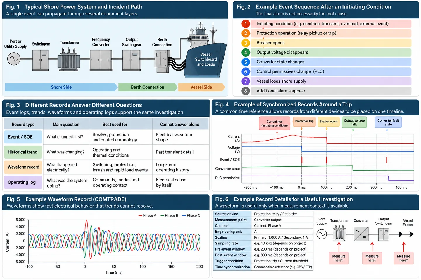
A single incident can change several parts of the system within a short period. A protection relay may operate. A breaker may open. The converter may stop. Output voltage disappears. PLC permissives change. The vessel detects loss of shore supply. Other alarms can then follow.
Every indication may be valid, but the alarm still visible after the trip is not necessarily the event that started the sequence.
A useful investigation therefore combines several types of records:
- Sequence-of-events records help establish which discrete changes occurred first.
- Historical trends show how operating conditions developed before and after the interruption.
- Waveform records capture fast electrical behavior around the event.
- Operating records add commands, mode changes and other context needed to interpret the sequence.
The objective is not to record as much data as possible. It is to preserve the right evidence, at the right time resolution, with enough context to separate the initiating event from the responses that followed it.
Why the Final Alarm May Not Be the Root Cause
A shore power system contains several protection, control and switching layers.
Depending on the project, an interruption may involve incoming switchgear, transformers, the frequency converter, output switchgear, berth connection equipment, protection relays, PLC controls and the vessel electrical system.
One initiating condition can therefore produce a sequence such as:
The later indications are not necessarily false. They simply describe different points in the same event chain.
A fault indication tells an engineer that a condition occurred. It does not by itself identify where the sequence began.
For that reason, fault diagnosis needs more than an active-alarm screen. Engineers need enough historical information to reconstruct protection actions, switching states, control changes and electrical conditions around the interruption.
In shore power monitoring projects, that information can include sequence-of-events records, historical curves, protection information, operating logs and disturbance records.
The diagnostic task is to put them into the correct order.
Start With a Common Event Timeline
Sequence-of-Events Records Establish Order
Sequence-of-events records are useful for discrete changes such as:
- breaker opening or closing
- protection pickup or trip
- converter ready, running or fault state
- PLC permissive changes
- emergency-stop inputs
- connection-ready signals
- relevant operator commands
- reset actions
The purpose is not to record every possible digital point in the control system. The useful question is:
If a protection relay operates before the converter enters fault state, the investigation follows a different path from a converter fault that appears before the output breaker opens.
That difference may be difficult to identify when several device logs are reviewed separately.
Why Time Synchronization Matters
A timestamp is only useful for cross-device diagnosis when timestamps from different devices can be compared with sufficient confidence.
A protection relay, converter controller and PLC may all record an incident. If their clocks have unknown offsets, the apparent order of those events may not represent the actual sequence.
A common time reference allows separate records to be placed on one incident timeline.
Precision time synchronization is an established part of power-system automation. The required accuracy still depends on the events being investigated. A slow thermal trend and a fast protection sequence do not require the same temporal resolution.
The project should therefore define:
- which devices need synchronized time
- the available synchronization method
- the event resolution required
- how synchronization status is monitored
- what happens if the time source is temporarily unavailable
In one shore power monitoring configuration, GPS-based synchronization provided the common time reference. That is one engineering implementation, not a universal requirement.
The system relationships behind these records are explained further in our shore power system architecture and components .
Event Logs, Trends and Waveforms Answer Different Questions
These records support the same investigation, but they perform different jobs.
| Record type | Main question | Best used for | Cannot answer alone |
|---|---|---|---|
| Event / SOE | What changed first? | Breaker, protection and control chronology | Electrical waveform shape |
| Historical trend | What was changing? | Operating and thermal conditions | Fast transient detail |
| Waveform record | What happened electrically? | Switching, protection, inrush and rapid load events | Long-term operating history |
| Operating log | What was the system doing? | Commands, modes and operating context | Electrical cause by itself |
Trends Show Developing Conditions
Historical trends help show the operating condition around an interruption.
Depending on the diagnostic scope, useful signals may include:
- voltage
- current
- frequency
- active and reactive power
- power factor
- transformer temperature
- converter temperature
- cooling or auxiliary-system status
A trend can show whether a condition was developing before the trip. A gradual temperature rise, for example, represents a different type of evidence from a sudden current transient.
Recording intervals should therefore follow the purpose of each signal. Slow thermal conditions and fast electrical events operate on different timescales.
Waveforms Show Fast Electrical Behavior
A historical trend may show normal voltage before an interruption and zero voltage afterward without revealing what happened between those two states.
For a fast event, engineers may need instantaneous voltage and current records to examine behavior such as:
- current rise
- voltage dip
- switching transient
- transformer energization
- motor starting
- rapid load application or rejection
- synchronization disturbance
- protection operation
A trend suitable for normal operating history may still be too slow to explain a fast switching or protection event.
Transient waveform and event data are established engineering record types in power systems. IEC 60255-24 defines the COMTRADE format for exchanging transient waveform, event, fault and test data.
COMTRADE is not a universal requirement for every shore power project, but standardized export can make disturbance records easier to exchange and review outside the originating device.
Preserve What Happened Before the Trip
A recorder that starts too late can preserve the system response while missing the condition that caused it.
If the record begins only at or after the trigger, part of the initiating electrical behavior may already have passed.
This is why disturbance recording can include both pre-event and post-event information.
Why Pre-Event Data Matters
Suppose a converter trips during transformer energization. The final event record may show only a converter trip, while the more useful diagnostic question is what happened to voltage and current immediately before the trip.
More detail on this specific transient is available in transformer inrush current in shore power systems .
The same principle applies when a large vessel load starts or when a synchronized transfer creates a rapid change in system conditions. Reverse-power behavior during transfer is discussed separately in reverse power during shore-to-ship transfer .
The pre-event window should be long enough to capture the condition leading into the trigger.
There is no universal pre-trigger duration for shore power systems. It depends on the event being investigated, the protection sequence, recorder capability and the purpose of the investigation.
A Waveform Is Useful Only When You Know Where It Was Measured
A waveform without measurement context can be difficult to interpret reliably.
A current record might come from:
- the port or utility incoming supply
- converter input
- converter output
- shore feeder
- vessel feeder
The same current increase can have a different meaning at each point.
A useful disturbance record therefore needs enough information to identify the signal and its location, including where relevant:
- source device
- measurement point
- channel
- phase
- engineering unit
- scaling information
If vessel-feeder current rises before a voltage disturbance, a vessel-side operating event may deserve investigation. If an upstream shore-side disturbance appears first while vessel current has not yet changed, the investigation moves in another direction.
A waveform should therefore be interpreted together with the single-line diagram and the event timeline rather than as an isolated picture.
Follow the Evidence Across the Shore–Vessel Power Path
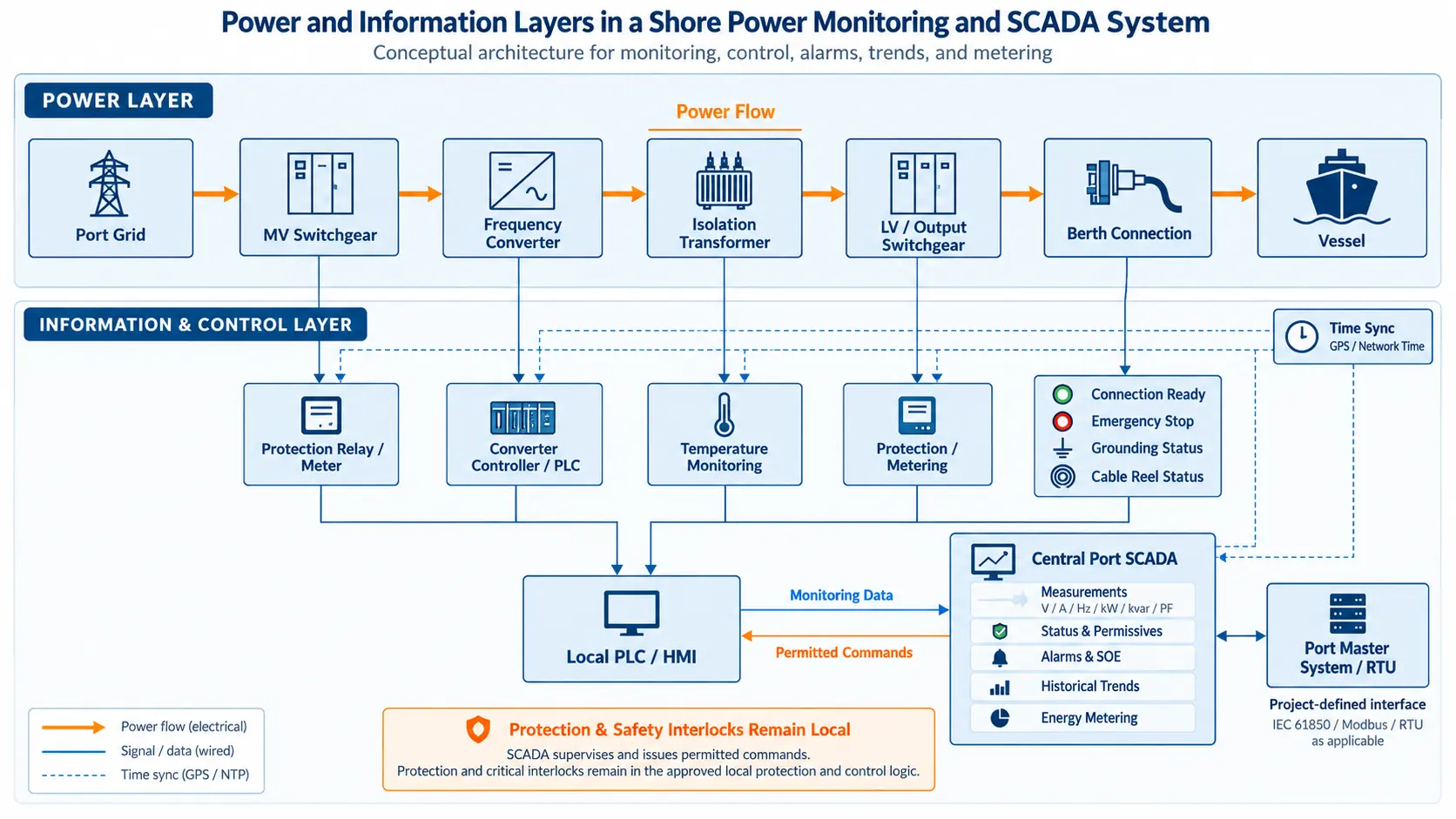
A shore power event can propagate through several equipment layers:
The device reporting the final trip is not necessarily the point where the event originated.
A converter fault indication, for example, can be part of the response to an upstream switching condition or a downstream electrical event.
The investigation should therefore follow the power and control path instead of stopping at the first device that reports a fault.
Compare Shore and Vessel Information Where Available
Some incidents cross the shore–ship boundary.
Relevant vessel-side information can include:
- generator-transfer status
- major load operation
- vessel switchboard state
- large motor starting
- connection and transfer sequence
In one vessel-connection project, the operating sequence included generator load transfer and onboard pump-start tests. These were controlled operating events rather than fault incidents, but they illustrate how vessel-side actions can create electrical changes visible on the shore system.
Where vessel-side records are available, comparison with shore-side data can help distinguish:
The amount of vessel-side information available varies between projects. That interface should be defined during system engineering rather than assumed after an incident.
For the broader equipment and connection context, see our commercial shore power systems .
Preserve the Record Long Enough to Investigate It
A fault record is useful only if it is still available when the engineering investigation begins.
This matters in shore power applications because operation can be intermittent. An event may occur during one vessel call while detailed technical review takes place later.
Additional events can be recorded in the meantime, and some recording systems can overwrite older disturbance records when their allocated storage becomes full.
Retention is therefore part of diagnostic design.
Retention Should Follow the Investigation Workflow
The required retention period depends on factors such as:
- vessel-call frequency
- expected event frequency
- reporting procedure
- likely delay before engineering review
- waveform file size
- contractual or regulatory recording requirements
The useful design question is not simply:
It is:
Export the Record for Engineering Review
Important records also need to be retrievable in a form engineers can use.
An investigation may require comparison of:
- relay events
- converter records
- SCADA history
- waveform files
- breaker states
- operating logs
The project should therefore define how relevant event and disturbance records can be exported for engineering review.
Include Operator Actions in the Incident Timeline
Not every important event is generated automatically.
The timeline may also include:
- manual breaker commands
- start or stop commands
- reset actions
- operating-mode changes
- parameter adjustments
Shore power control projects can record relevant operations and parameter changes so they remain available during later investigation.
A command immediately before a trip may be relevant, but the electrical measurements, protection records and equipment response still need to establish how that action relates to the event.
The operating log completes the timeline. It does not assign blame.
Verify the Recording Chain Before the First Real Incident
A history page on an HMI does not prove that the available records will be sufficient after a real trip.
The recording chain should be checked under controlled conditions during FAT or commissioning.
A practical verification can follow a known event from beginning to end.
1. Create a Known Event
Use an approved test condition such as a simulated alarm, controlled state transition, permitted breaker operation or controlled electrical event.
2. Confirm the Local Device Record
Check that the relevant relay, controller or converter identifies the expected event and records the required timestamp and state.
3. Check PLC, HMI and SCADA Records
Confirm that the event reaches the expected higher-level system and appears in a consistent sequence.
4. Check the Historical Trend
Verify that useful operating data are available before and after the event.
5. Check the Disturbance Record
Where waveform recording is required, verify:
- trigger operation
- pre-event data
- post-event data
- correct channels
- phase identification
- measurement location
- scaling
6. Compare Device Timing
Confirm that records from separate devices can be placed on a usable common timeline.
7. Export the Records
Check that an engineer can retrieve the event and waveform files outside the live HMI session.
8. Reconstruct the Known Event
The final question is simple:
In project testing, waveform recording has been used throughout controlled tests so that electrical responses could be reviewed afterward.
That same principle can be applied to the diagnostic recording chain before commissioning is complete. For related manufacturing and verification work, see shore power manufacturing and FAT .
Define the Diagnostic Recording Scope Before Procurement
A specification that says only “monitoring system with alarm history” does not define a complete fault-diagnosis capability.
The recording scope should be agreed before equipment selection and control-system configuration are complete.
Event Records
- required protection events
- breaker states
- important control states
- relevant operator actions
- event-resolution requirement
Time Synchronization
- devices requiring synchronization
- supported synchronization method
- required timing accuracy
- response to loss of the time source
Historical Trends
- required channels
- recording intervals
- retention
Waveform Records
- electrical channels
- measurement points
- trigger conditions
- pre-event window
- post-event window
- required sampling capability
Data Handling
- retention
- storage and overwrite behavior
- export requirements
- backup requirements where applicable
Shore–Vessel Information
- vessel-side signals available to the shore system
- transfer and operating information that can be retained
- responsibility for post-event data collection
Verification
- FAT recording checks
- commissioning or SAT checks
- required exported test evidence
These requirements should follow the diagnostic problems the project actually needs to solve.
Higher sampling rates, more recording channels and longer retention can provide more information, but they also increase storage, configuration, integration and review effort.
Frequently Asked Questions
What is the difference between an event log and a trend?
An event log records discrete changes such as a breaker opening, protection operation or control-state change with a timestamp.
A trend records how a measured value such as voltage, current, power or temperature changes over time. They answer different diagnostic questions and are often used together.
When is waveform recording needed?
Waveform recording is useful when an investigation depends on fast electrical behavior that ordinary historical trends cannot resolve adequately.
Examples include switching events, protection operation, transformer energization, rapid load changes and synchronization-related disturbances. The required channels and sampling capability depend on the project.
Why does time synchronization matter in shore power fault diagnosis?
Because event records can come from several devices. If relay, converter, PLC and SCADA timestamps cannot be compared reliably, engineers may not be able to determine which event occurred first.
The required synchronization method and accuracy depend on the events that need to be distinguished.
How long should shore power fault records be retained?
There is no universal retention period. Retention should reflect vessel-call frequency, event frequency, reporting requirements and the realistic delay between an incident and engineering review.
Critical disturbance records also need to remain available before they are overwritten.
Can an HMI automatically identify the root cause of a shore power trip?
An HMI can present alarms, trends and event history, but those records still require engineering interpretation.
Root-cause diagnosis may require event chronology, electrical measurements, protection records, waveform data and shore–vessel operating context. A final alarm alone cannot reconstruct every incident.
Technical References
- IEC/IEEE 80005-1 — High-voltage shore connection systems; system scope includes control, monitoring, interlocking and power-management functions.
- IEC 60255-24 — COMTRADE format for transient waveform, event, fault and test data.
- IEC/IEEE 61850-9-3 — Precision time protocol profile for power utility automation.
Build Fault Records Before the First Incident
Fault diagnosis is much easier when the recording scope is defined before commissioning rather than after the first unexplained trip.
For an engineering review, provide the available:
- single-line diagram
- protection and control architecture
- required event signals
- timing and synchronization requirements
- trend channels
- waveform measurement points
- trigger requirements
- retention and export requirements
- FAT or SAT recording scope
SDACME can review how event records, trends, disturbance waveforms and control-system data should work together within the shore power system.
Send Your Project Requirements